
Fluorescent Dyes
This entry is from Wikipedia, the leading user-contributed encyclopedia.
• Fluorescence
• Fluorescent tag
• Fluorescence resonance energy transfer
• Immunofluorescence
• Fluorophore
• Carboxyfluorescein
• IAEDANS
• Rhodamine
• Quenching
• Dark quencher
• Phycocyanin
• Phycoerythrin
Fluorescence
Fluorescence is a luminescence that is mostly found as an optical phenomenon in cold bodies, in which the molecular absorption of a photon triggers the emission of another photon with a longer wavelength. The energy difference between the absorbed and emitted photons ends up as molecular vibrations or heat. Usually the absorbed photon is in the ultraviolet range, and the emitted light is in the visible range, but this depends on the absorbance curve and Stokes shift of the particular fluorophore. Fluorescence is named after the mineral fluorite, composed of calcium fluoride, which often exhibits this phenomenon.
Contents
1. Equations
1.1. Photochemistry
1.2. Fluorescence quantum yield
1.3. Fluorescence lifetime
2. Rules
3. Applications
3.1. Lighting
3.2. Analytical chemistry
4. Biochemistry and medicine
4.1. References
4.2. External links
5. Gemology, mineralogy, geology and forensics
6. Organic liquids
1. Equations
1.1. Photochemistry
Fluorescence occurs when a molecule or quantum dot relaxes to its ground state after being electronically excited.
Excitation: ![]()
Fluorescence (emission): ![]() , here hν is a generic term for photon energy where: h = Planck’s constant and ν = frequency of light. (The specific frequencies of exciting and emitted light are dependent on the particular system.)
, here hν is a generic term for photon energy where: h = Planck’s constant and ν = frequency of light. (The specific frequencies of exciting and emitted light are dependent on the particular system.)
State S0 is called the ground state of the fluorophore (fluorescent molecule) and S1 is its first (electronically) excited state.
A molecule in its excited state, S1, can relax by various competing pathways. It can undergo ‘non-radiative relaxation’ in which the excitation energy is dissipated as heat (vibrations) to the solvent. Excited organic molecules can also relax via conversion to a triplet state which may subsequently relax via phosphorescence or by a secondary non-radiative relaxation step.
Relaxation of an S1 state can also occur through interaction with a second molecule through fluorescence quenching. Molecular oxygen (O2) is an extremely efficient quencher of fluorescence because of its unusual triplet ground state.
Molecules that are excited through light absorption or via a different process (e.g. as the product of a reaction) can transfer energy to a second ‘sensitized’ molecule, which is converted to its excited state and can then fluoresce. This process is used in lightsticks.
1.2. Fluorescence quantum yield
The fluorescence quantum yield gives the efficiency of the fluorescence process. It is defined as the ratio of the number of photons emitted to the number of photons absorbed.
The maximum fluorescence quantum yield is 1.0 (100%); every photon absorbed results in a photon emitted. Compounds with quantum yields of 0.10 are still considered quite fluorescent. Another way to define the quantum yield of fluorescence, is by the rates excited state decay:
where kf is the rate of spontaneous emission of radiation and
∑ ki
i
is the sum of all rates of excited state decay. Other rates of excited state decay are caused by mechanisms other than photon emission and are therefore often called “non-radiative rates”, which can include: dynamic collisional quenching, near-field dipole-dipole interaction (or resonance energy transfer), internal conversion and intersystem crossing. Thus, if the rate of any pathway changes, this will affect both the excited state lifetime and the fluorescence quantum yield.
Fluorescence quantum yield are measured by comparison to a standard with known quantology; the quinine salt, quinine sulfate, in a sulfuric acid solution is a common fluorescence standard.
1.3. Fluorescence lifetime
The fluorescence lifetime refers to the average time the molecule stays in its excited state before emitting a photon. Fluorescence typically follows first-order kinetics:
where![]() is the concentration of excited state molecules at time t,
is the concentration of excited state molecules at time t, ![]() is the initial concentration and Γ is the decay rate or the inverse of the fluorescence lifetime. This is an instance of exponential decay. Various radiative and non-radiative processes can de-populate the excted state. In such case the total decay rate is the sum over all rates:
is the initial concentration and Γ is the decay rate or the inverse of the fluorescence lifetime. This is an instance of exponential decay. Various radiative and non-radiative processes can de-populate the excted state. In such case the total decay rate is the sum over all rates:
Γtot = Γrad + Γnrad
where Γtot is the total decay rate, Γrad the radiative decay rate and Γnrad the non-radiative decay rate. It is similar to a first-order chemical reaction in which the first-order rate constant is the sum of all of the rates (a parallel kinetic model). If the rate of spontaneous emission, or any of the other rates are fast, the lifetime is short. For commonly used fluorescent compounds typical excited state decay times for fluorescent compounds that emit photons with energies from the UV to near infrared are within the range of 0.5 to 20 nanoseconds. The fluorescence lifetime is an important parameter for practical applications of fluorescence such as fluorescence resonance energy transfer.
2. Rules
There are several rules that deal with fluorescence. The Kasha – Vavilov rule dictates that the quantum yield of luminescence is independent of the wavelength of exciting radiation.
This is not quite true and is violated severely in many simple molecules. A somewhat more reliable statement, although still with exceptions, would be that the fluorescence spectrum shows very little dependence on the wavelength of exciting radiation.
The Jablonski diagram describes most of the relaxation mechanism for excited state molecules.
3. Applications
There are many natural and synthetic compounds that exhibit fluorescence, and they have a number of applications. Some deep-sea animals, such as the Greeneye, use fluorescence.
3.1. Lighting
The common fluorescent tube relies on fluorescence. Inside the glass tube is a partial vacuum and a small amount of mercury. An electric discharge in the tube causes the mercury atoms to emit light. The emitted light is in the ultraviolet (UV) range and is invisible, and also harmful to living organisms, so the tube is lined with a coating of a fluorescent material, called the phosphor, which absorbs the ultraviolet and re-emits visible light. Fluorescent lighting is very energy efficient compared to incandescent technology, but the spectra produced may cause certain colours to appear unnatural. Some claim they may lead to adverse health effects, though that has not been verified. And as with all light sources, over-illumination is possible.
In the mid 1990s, white light-emitting diodes (LEDs) became available, which work through a similar process. Typically, the actual light-emitting semiconductor produces light in the blue part of the spectrum, which strikes a phosphor compound deposited on the chip; the phosphor fluoresces from the green to red part of the spectrum. The combination of the blue light that goes through the phosphor and the light emitted by the phosphor produce a net emision of white light.
The modern mercury vapor streetlight is said to have been evolved from the fluorescent lamp.
Glow sticks oxidise phenyl oxalate ester in order to produce light.
Compact fluorescent lighting (CFL) is the same as any typical fluorescent lamp with advantages. It is self-ballasted and used to replace incandescents in most applications. They produce a quarter of the heat per lumen as incandescent bulbs and last about five times as long. These bulbs contain mercury and must be handled and disposed with care.
3.2. Analytical chemistry
Fluorescence in several wavelenghts can be detected by an array detector, to detect compounds from HPLC flow. Also, TLC plates can be visualized if the compounds or a coloring reagent is fluorescent.
Fingerprints can be visualized with fluorescent compounds such as ninhydrin.
4. Biochemistry and medicine
There is a wide range of applications for fluorescence in this field. Biological molecules can be tagged with a fluorescent chemical group (fluorophore) by a simple chemical reaction, and the fluorescence of the tag enables sensitive and quantitative detection of the molecule. Examples:
• Fluorescence microscopy of tissues, cells or subcellular structures is accomplished by labeling an antibody with a fluorophore and allowing the antibody to find its target antigen within the sample. Labeling multiple antibodies with different fluorophores allows visualization of multiple targets within a single image.
• Automated sequencing of DNA by the chain termination method; each of four different chain terminating bases has its own specific fluorescent tag. As the labeled DNA molecules are separated, the fluorescent label is excited by a UV source, and the identity of the base terminating the molecule is identified by the wavelength of the emitted light.
• DNA detection: the compound ethidium bromide, when free to change its conformation in solution, has very little fluorescence. Ethidium bromide’s fluorescence is greatly enhanced when it binds to DNA, so this compound is very useful in visualising the location of DNA fragments in agarose gel electrophoresis. Ethidium bromide can be toxic – a safer alternative is the dye SYBR Green.
• The DNA microarray
• Immunology: An antibody has a fluorescent chemical group attached, and the sites (e.g., on a microscopic specimen) where the antibody has bound can be seen, and even quantified, by the fluorescence.
• FACS (fluorescent-activated cell sorting)
• Fluorescence has been used to study the structure and conformations of DNA and proteins with techniques such as Fluorescence resonance energy transfer, which measures distance at the angstrom level. This is especially important in complexes of multiple biomolecules.
• Aequorin, from the jellyfish Aequorea victoria, produces a blue glow in the presence of Ca2+ ions (by a chemical reaction). It has been used to image calcium flow in cells in real time. The success with aequorin spurred further investigation of A. victoria and led to the discovery of Green Fluorescent Protein (GFP), which has become an extremely important research tool. GFP and related proteins are used as reporters for any number of biological events including such things as sub-cellular localization. Levels of gene expression are sometimes measured by linking a gene for GFP production to another gene.
Also, many biological molecules have an intrinsic fluorescence that can sometimes be used without the need to attach a chemical tag. Sometimes this intrinsic fluorescence changes when the molecule is in a specific environment, so the distribution or binding of the molecule can be measured. Bilirubin, for instance, is highly fluorescent when bound to a specific site on serum albumin. Zinc protoporphyrin, formed in developing red blood cells instead of hemoglobin when iron is unavailable or lead is present, has a bright fluorescence and can be used to detect these problems.
As of 2006, the number of fluorescence applications is growing in the biomedical biological and related sciences. Methods of analysis in these fields are also growing, albeit with increasingly unfortunate nomenclature in the form of acronyms such as: FLIM, FLI, FLIP, CALI, FLIE, FRET, FRAP, FCS, PFRAP, smFRET, FIONA, FRIPS, SHREK, SHRIMP, TIRF. Most of these techniques rely on fluorescence microscopes. These microscopes use high intensity light sources, usually mercury or xenon lamps, LEDs, or lasers, to excite fluorescence in the samples under observation. Optical filters then separate excitation light from emitted fluorescence, to be detected by eye, or with a (CCD) camera or other light detectors (photomultiplier tubes, spectrographs, etc). Much research is underway to improve the capabilities of such microscopes, the fluorescent probes used, and the applications they are applied to. Of particular note are confocal microscopes, which use a pinhole to achieve optical sectioning – affording a quantitative, 3D view of the sample.
5. Gemology, mineralogy, geology and forensics
Gemstones, minerals, fibers and many other materials which may be encountered in forensics or with a relationship to various collectibles may have a distinctive fluorescence or may fluoresce differently under short-wave ultraviolet, long-wave ultra violet, or X-rays.
Many types of calcite and amber will fluoresce under shortwave UV. Rubies, emeralds, and the Hope Diamond exhibit red fluorescence under short-wave UV light; diamonds also emit light under X ray radiation. Fluorescence can also be used to help recognise chirality in minerals [citation needed].
Crude oil (Petroleum) fluoresces in a range of colors, from dull brown for heavy oils and tars through to bright yellowish and bluish white for very light oils and condensates. This phenomenon is used in oil exploration drilling to identify very small amounts of oil in drill cuttings and core sample.
6. Organic liquids
Organic liquids such as mixtures of anthracene in benzene or toluene, or stilbene in the same solvents, fluoresce with ultraviolet or gamma ray irradiation. The decay times of this fluorescence is of the order of nanoseconds since the duration of the light depends on the lifetime of the excited states of the fluorescent material, in this case anthracene or stilbene.
Fluorescent tag
In molecular biology and biotechnology, a fluorescent tag is a part of a molecule that researchers have attached chemically to aid in detection of the molecule to which it has been attached. The tag is some kind of fluorescent molecule (also known as fluorophore). Fluorescein and Green fluorescent protein are common tags.
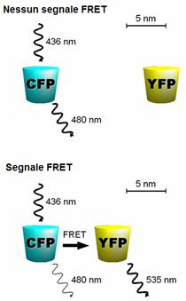
Fluorescence resonance energy transfer
Fluorescence resonance energy transfer (FRET) describes an energy transfer mechanism between two chromophores.
A donor chromophore in its excited state can transfer energy by a nonradiative, long-range dipole-dipole coupling mechanism to an acceptor chromophore in close proximity (typically <10nm). This energy transfer mechanism is termed “Förster resonance energy transfer” (FRET), named after the German scientist Theodor Förster. When both molecules are fluorescent, the term “fluorescence resonance energy transfer” is often used, although the energy is not actually transferred by fluorescence.[2] In order to avoid an erroneous interpretation of the phenomenon that, even when occurring between two fluorescent molecules, is always a nonradiative transfer of energy, the name “Förster resonance energy transfer” may be preferred to “Fluorescence resonance energy transfer”.
Fluorescent proteins localize the guanosine 5′-triphosphate hydrolase ARF in the Golgi apparatus of a living macrophage. FRET studies revealed ARF activation in the Golgi and in the formation of phagosomes.[1]
Contents
1. Theoretical basis
2. Methods
2.1. CFP-YFP pairs
2.2. BRET
2.3. Other methods
3. Applications
4. References
1. Theoretical basis
The FRET efficiency (E) is the quantum yield of the energy transfer transition, i.e. the fraction of energy tranfer event occurring per donor excitation event:
where kET is the rate of energy transfer, kf the radiative decay rate and the ki are the rate constants of any other de-excitation pathway.
The FRET efficiency depends on many parameters that can be grouped as follows:
• The distance between the donor and the acceptor
• The spectral overlap of the donor emission spectrum and the acceptor absorption spectrum.
• The relative orientation of the donor emission dipole moment and the acceptor absorption dipole moment.
E depends on the donor-to-acceptor separation distance r with an inverse 6th power law due to the dipole-dipole coupling mechanism:
with R0 being the Förster distance of this pair of donor and acceptor at which the FRET efficiency is 50%. The Förster distance depends on the overlap integral of the donor emission spectrum with the acceptor absorption spectrum and their mutual molecular orientation as expressed by the following equation:
where κ2 is the dipole orientation factor, n is the refractive index of the medium, Q0 is the fluorescence quantum yield of the donor in the absence of the acceptor, and J is the spectral overlap integral calculated as
where fD is the normalized donor emission spectrum, and εA is the acceptor molar extinction coefficient. κ2 =2/3 is often assumed. This value is obtained when both dyes are freely rotating and can be considered to be isotropically oriented during the excited state lifetime. If either dye is fixed or not free to rotate, then κ2 =2/3 will not be a valid assumption. In most cases, however, even modest reorientation of the dyes results in enough orientational averaging that κ2 = 2/3 does not result in a large error in the estimated energy transfer distance due to the sixth power dependence of R0 on κ2. Even when κ2 is quite different from 2/3 the error can be associated with a shift in R0 and thus determinations of changes in relative distance for a particular system are still valid. Fluorescent proteins do not reorient on a timescale that is faster than their fluorescence lifetime. In this case 0 ≤ κ2 ≤ 4.
The FRET efficiency relates to the quantum yield and the fluorescence lifetime of the donor molecule as follows:
where τ’D and τD are the donor fluorescence lifetimes in the presence and absence of an acceptor, respectively, or as
where F’D and FD are the donor fluorescence intensities with and without an acceptor, respectively.
2. Methods
Example of FRET between CFP and YFP (Wavelength vs. Absorption): a fusion protein containing CFP and YFP excited at 440nm wavelength. The fluorescent emission peak of CFP overlaps the excitation peak of YFP. Because the two proteins are adjacent to each other, the energy transfer is significant–a large proportion of the energy from CFP is transferred to YFP and creates a much larger YFP emission peak.In fluorescence microscopy, fluorescence confocal laser scanning microscopy, as well as in molecular biology, FRET is a useful tool to quantify molecular dynamics in biophysics and biochemistry, such as protein-protein interactions, protein-DNA interactions, and protein conformational changes. For monitoring the complex formation between two molecules, one of them is labeled with a donor and the other with an acceptor, and these fluorophore-labeled molecules are mixed. When they are dissociated, the donor emission is detected upon the donor excitation. On the other hand, when the donor and acceptor are in proximity (1-10 nm) due to the interaction of the two molecules, the acceptor emission is predominantly observed because of the intermolecular FRET from the donor to the acceptor. For monitoring protein conformational changes, the target protein is labeled with a donor and an acceptor at two loci. When a twist or bend of the protein brings the change in the distance or relative orientation of the donor and acceptor, FRET change is observed. If a molecular interaction or a protein conformational change is dependent on ligand binding, this FRET technique is applicable to fluorescent indicators for the ligand detection.
FRET studies are scalable: the extent of energy transfer is often quantified from the milliliter scale of cuvette-based experiments to the femtoliter scale of microscopy-based experiments. This quantification can be based directly (sensitized emission method) on detecting two emission channels under two different excitation conditions (primarily donor and primarily acceptor). However, for robustness reasons, FRET quantification is most often based on measuring changes in fluorescence intensity or fluorescence lifetime upon changing the experimental conditions (e.g. a microscope image of donor emission is taken with the acceptor being present. The acceptor is then bleached, such that it is incapable of accepting energy transfer and another donor emission image is acquired. A pixel-based quantification using the second equation in the theory section above is then possible.) An alternative way of temporarily deactivating the acceptor is based on its fluorescence saturation. Exploiting polarisation characteristics of light, a FRET quantification is also possible with only a single camera exposure.
2.1. CFP-YFP pairs
The most popular FRET pair for biological use is a cyan fluorescent protein (CFP)-yellow fluorescent protein (YFP) pair. Both are color variants of green fluorescent protein (GFP). While labeling with organic fluorescent dyes requires troublesome processes of purification, chemical modification, and intracellular injection of a host protein, GFP variants can be easily attached to a host protein by genetic engineering. By virtue of GFP variants, the use of FRET techniques for biological research is becoming more and more popular.
2.2. BRET
A limitation of FRET is the requirement for external illumination to initiate the fluorescence transfer, which can lead to background noise in the results from direct excitation of the acceptor or to photobleaching. To avoid this drawback, Bioluminescence Resonance Energy Transfer (or BRET) has been developed. This technique uses a bioluminescent luciferase (typically the luciferase from Renilla reniformis) rather than CFP to produce an initial photon emission compatible with YFP.
FRET and BRET are also the common tools in the study of biochemical reaction kinetics and molecular motors.
2.3. Other methods
A different, but related, mechanism is Dexter Electron Transfer.
An alternative method to detecting protein-protein proximity is BiFC where two halves of a YFP are fused to a protein (Hu, Kerppola et al. 2002). When these two halves meet they form a fluorophore after about 60 s – 1 hr.
3. Applications
FRET has been applied in an experimental method for the detection of phosgene. In it, phosgene or rather triphosgene as a safe substitute serves as a linker between an acceptor and a donor coumarine (forming urea groups).[3] The presence of phosgene is detected at 5×10⁻⁵M with a typical FRET emission at 464 nm.
4. References
1. Inconspicuous Consumption: Uncovering the Molecular Pathways behind Phagocytosis. Inman M, PLoS Biology Vol. 4/6/2006
2. Joseph R. Lakowicz, “Principles of Fluorescence Spectroscopy”, Plenum Publishing Corporation, 2nd edition (July 1, 1999)
3. A FRET approach to phosgene detection Hexiang Zhang and Dmitry M. Rudkevich Chem. Commun., 2007, 1238 – 1239
Immunofluorescence
Immunofluorescence is the labeling of antibodies or antigens with fluorescent dyes. This technique is often used to visualize subcellular distribution of biomolecules of interest. Immunofluorescent labelled tissue sections are studied using a fluorescence microscope or by confocal microscopy.
Most commonly, immunofluorescence employs two sets of antibodies: a primary antibody is used against the antigen of interest; a subsequent, secondary, dye-coupled antibody is introduced that recognizes the primary antibody. In this fashion the researcher may create several primary antibodies that recognize various antigens, but, because they all share a common constant region, may be recognized by a single dye-coupled antibody. Typically this is done by using antibodies made in different species. For example, a researcher might create antibodies in a goat that recognize several antigens, and then employ dye-coupled rabbit antibodies that recognize the goat antibody constant region (denoted rabbit anti-goat). This allows re-use of the difficult-to-make dye-coupled antibodies in multiple experiments.
In some cases, it is advantageous to use primary antibodies directly labelled with a fluorophore. This direct labelling decreases the number of steps in the staining procedure and, more importantly, often avoids cross-reactivity and high background problems. Fluorescent labelling can be performed in less than one hour with readily available labeling kits.
As with most fluorescence techniques, a significant problem with immunofluorescence is photobleaching. Loss of activity caused by photobleaching can be controlled by reducing the intensity or time-span of light exposure, by increasing the concentration of fluorophores, or by employing more robust fluorophores that are less prone to bleaching (e.g. Alexa Fluors or DyLight Fluors).
Many uses of immunofluorescence have been outmoded by the development of recombinant proteins containing fluorescent protein domains, e.g. green fluorescent protein (GFP). Use of such “tagged” proteins allows much better localization and less disruption of protein function.
External links
• Immunofluorescence Staining and Immunocytochemistry Protocol
• Immunohistochemistry – In Situ Hybridization
• Immunofluorescence Staining Protocol
• Immunofluorescence
Fluorophore
A fluorophore, in analogy to a chromophore, is a component of a molecule which causes a molecule to be fluorescent. It is a functional group in a molecule which will absorb energy of a specific wavelength and re-emit energy at a different (but equally specific) wavelength. The amount and wavelength of the emitted energy depend on both the fluorophore and the chemical environment of the fluorophore. This technology has particular importance in the field of biochemistry and protein studies, eg. in immunofluorescence and immunohistochemistry.
Fluorescein isothiocyanate, a reactive derivative of fluorescein, has been one of the most common fluorophores chemically attached to other, non-fluorescent molecules to create new and fluorescent molecules for a variety of applications. Other historically common fluorophores are derivatives of rhodamine, coumarin and cyanine.
A newer generation of fluorophores such as the Alexa Fluors and the DyLight Fluors are generally more photostable, brighter, and less pH-sensitive than other standard dyes of comparable excitation and emission.
Size
The size of the fluorophore might sterically hinder the tagged molecule:
• quantum dot: 2-10 nm (diameter), 100-100,000 atoms
• Green fluorescent protein (GFP) 26 kDa
• luciferin: about 20 atoms
External links
• Immunofluorescence Staining Protocol
• Fluorescence SpectraViewer
Carboxyfluorescein
Carboxyfluorescein is a fluorescent dye with an excitation and emission of 492/517 nm, respectively. It is commonly used as a tracer agent. The dye is membrane-impermeant and can be loaded into cells by microinjection or scrape loading. It can be incoporated into liposomes, and allow for the tracking of liposomes as they pass through the body. In addition, Carboxyfluorescein has been used to track division of cells.[1]
Carboxyfluorescein | ||
Common name | 6-FAM | |
Systematic name | 2′,7′-bis(2-Carboxyethyl)-5(6)-carboxyfluorescein | |
Chemical formula | C27H20O11 | |
FW | 376.3 | |
CAS number | 85138-49-4 | |
Notes
1. Parish, Christopher (1999-12). Fluorescent dyes for lymphocyte migration and proliferation studies. Immunology and Cell Biology. Blackwell Synergy.
IAEDANS
IAEDANS is an organic fluorophore (fluorescent molecule). It stands for 5-({[(2-iodoacetyl)amino]ethyl}amino)-naphthalene-1-sulphonic acid. It is widely use like a marker in fluorescence spectroscopy. The molecular weight of 1,5-IAEDANS is 434.25 g/mol, with a peak excitation wavelength of 336 nm and a peak emission wavelength of 490 nm. The extinction coefficient of the dye is 5700. It is soluble in dimethylformamide (DMF) above pH 6 and reacts primarily with thiols. The emission spectrum of IAEDANS overlaps well with the absorption spectra of fluorescein, Alexa Fluor 488, Oregon Green, and BODIPYFL dyes, making it a useful donor for FRET experiments.

Rhodamine
Rhodamine is a family of related chemical compounds, fluorone dyes. Examples are Rhodamine 6G and Rhodamine B. They are used as a dye and as a dye laser gain medium. It is often used as a tracer dye within water to determine the rate and direction of flow and transport. Rhodamine dyes fluoresce and can thus be measured easily and inexpensively with instruments called fluorimeters. Rhodamine dyes are used extensively in biotechnology applications such as fluorescence microscopy, flow cytometry and ELISA
Rhodamine dyes are generally toxic, and are soluble in water, methanol, and ethanol.
1. Rhodamine B
Molecular Formula: C28H31N2O3Cl
Molecular Weight: 479.02 grams per mole
CAS Number: 81-88-9
SMILES structure: [Cl-].CCN(CC)c1ccc2c(OC3=CC(C=CC3=C2c4ccccc4C(O)=O)=[N+](CC)CC)c1
Rhodamine B is used in biology as a staining fluorescent dye, sometimes in combination with auramine O, as the auramine-rhodamine stain to demonstrate acid-fast organisms, notably Mycobacterium.
Rhodamine B is tunable around 610 nm when used as a laser dye.
Rhodamine B is also called Rhodamine 610, Basic Violet 10, or C.I. 45170.
2. Rhodamine 6G
Molecular Formula: C28H31N2O3Cl
Molecular Weight: 479.02 g/mol
CAS Number: 989-38-8
SMILES structure: [Cl-].CCNc1cc2OC3=CC(=[NH+]CC)C(=CC3=C(c2cc1C)c4ccccc4C(=O)OCC)C
Rhodamine 6G is often used as a laser dye, and is pumped by the 2nd (532 nm) harmonic from a Nd:YAG laser. The dye has a remarkably high photostability, high quantum yield, low cost, and its lasing range has close proximity to its absorption maximum (approximately 530 nm). The lasing range of the dye is 555 to 585 nm with a maximum at 566 nm.
Rhodamine 6G is also called Rhodamine 590, R6G, Basic Rhodamine Yellow , or C.I. 45160.
3. Rhodamine 123
The laser dye rhodamine 123 is also used in biochemistry to inhibit mitochondrion function. Rhodamine 123 seems to bind to the mitochondrion membranes and inhibit transport processes, especially the electron transport chain, thus slowing down inner respiration. It is a substrate of P-glycoprotein (Pgp), which is usually overexpressed in cancer cells. Recent reports indicate that rhodamine 123 may be also a substrate of multidrug resistance-associated protein (MRP), or more specifically, MRP1.
4. Other Rhodamine Derivatives
There are many rhodamine derivatives used for imaging purposes, for example the tetramethyl rhodamine derivatives TRITC and TAMRA, Texas Red and Rhodamine Red. TRITC is the base rhodamine molecule functionalized with an isothiocyanate group (-N=C=S), replacing a hydrogen atom on the bottom ring of the structure. This derivative is reactive towards amine groups on proteins inside cells. A succinimidyl-ester functional group attached to the rhodamine core, creating NHS-rhodamine, forms another common amine-reactive derivative.
Other derivatives of rhodamine include newer fluorophores such as Alexa 546, Alexa 555 and DyLight 549, have been tailored for various chemical and biological applications where higher photostability, increased brightness, different spectral characteristics, or different attachment groups are needed.
5. External links
• Absorption and Emission Spectra of Rhodamine B
• Absorption and Emission Spectra of Rhodamine 6G
• Absorption and Emission Spectra of Rhodamine 123
Quenching
Quenching refers to any process which decreases the fluorescence intensity of a given substance. A variety of processes can result in quenching, such as excited state reactions, energy transfer, complex formation and collisional quenching. As a consequence, quenching is often heavily dependent on pressure and temperature. Molecular oxygen and the iodide ion are common chemical quenchers.
Quenching poses a problem for non-instant spectroscopic methods, such as laser-induced fluorescence.
Quenching is made use of in optode sensors; for instance the quenching effect of oxygen on certain rubidium complexes allows the measurement of oxygen saturation in solution.
Dark quencher
A quencher is a non-fluorescent dye that absorbs light but does not emit it. It is used in molecular biology in conjunction with regular fluorophores: when they are within range no emissions are detected but when they are separated the flourophore’s emission is detected.
1. SNP Genotyping Example
An example of its use is in Taqman or invader assay, SNP genotyping methods. for example a hairpin loop with a fluorophore and quencher at the base of the stem is used: a unlabelled SNP specific PCR primer (one of many) with a specific 5′ tail binds to the sequence to be probed, the taq polymerase extends the sequence that will have a specific 5′ end dependent on the SNP (insensitive to polymorphisms upstream of the SNP in question), in the next run a primer, complementary to that tail, with a haipin loop is extended, in the next run the elongation of the complementary strand will linearise the hairpin separating the fluorophore and quencer. An alternative to using quenchers is by using FRET where the combination of two dyes gives a signal.
2. Examples of dark quenchers
Dabcyl (dimethylaminoazosulphonic acid) absorbs in the green spectrum and is often used with flourescein. (Dabsyl has a nearly identical absorption but has a sulphonyl choride to form more stable conjugates, instead of a succinimidyl ester). Black Hole Quenchers (Biosearch Technologies) are capable of quenching across the entire visible spectrum. Qxl quenchers from AnaSpec span the full visible spectrum. Iowa black FQ absorbs in the green-yellow part of the spectrum. Iowa black RQ blocks in the orange-red part of the spectrum.
3. Why are dark quenchers dark?
Dark quenchers are dyes with no native fluorescence. Until the last few years, quenchers have typically been a second fluorescent dye, for example, fluorescein as the reporter and rhodamine as the quencher (FAM/TAM probes). However, quencher fluorescence can increase background noise due to overlap between the quencher and reporter fluorescence spectra. This limitation often necessitates the use of complex data analysis and optical filters. Dark quenchers offer a solution to this problem because they do not occupy an emission bandwidth. Furthermore, dark quenchers enable multiplexing (when two or more reporter-quencher probes are used together).
Fluorescent dyes absorb light, which places the dye in an excited state; the dye returns to the ground state from the excited state by emitting light (fluorescence). In a reporter – quencher system the dye nonradiatively (without light) transfers energy to the quencher. This returns the dye to the ground state and generates the quencher excited state. The quencher then returns to the ground state through emissive decay (fluorescence) or nonradiatively (dark quenching). In nonradiative or dark decay, energy is given off via molecular vibrations (heat). (It should be noted that with the typical μM or less concentration of probe, the heat from radiationless decay is too small to effect the temperature of the solution.)
4. Quenching Mechanisms
There are a few distinct mechanisms by which energy can be transferred nonradiatively (without absorption or emission of photons) between two dyes, a donor and an acceptor. Förster resonance energy transfer (FRET or FET) is a dynamic quenching mechanism because energy transfer occurs while the donor is in the excited state. FRET is based on classical dipole-dipole interactions between the transition dipoles of the donor and acceptor and is extremely dependent on the donor – acceptor distance (R), falling off at a rate of 1/R6. FRET also depends on the donor-acceptor spectral overlap (see figure below) and the relative orientation of the donor and acceptor transition dipole moments. FRET can typically occur over distances up to 100 Å.
Dexter (also known as exchange or collisional energy transfer) is another dynamic quenching mechanism. Dexter energy transfer is a short-range phenomenon that decreases with e-R and depends on spatial overlap of donor and quencher molecular orbitals. In most donor fluorophore – quencher acceptor situations, the Förster mechanism is more important than the Dexter mechanism. With both Förster and Dexter energy transfer, the shapes of the absorption and fluorescence spectra of the dyes are unchanged. Exciplex (excited state complex) formation is a third dynamic quenching mechanism.
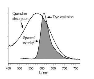
Donor emission and quencher absorption spectral overlap
The remaining energy transfer mechanism is static quenching (also referred to as contact quenching). Static quenching can be a dominant mechanism for some reporter-quencher probes. Unlike dynamic quenching, static quenching occurs when the donor and acceptor molecules are in the ground state. The donor and acceptor molecules bind together to form a ground state complex, an intramolecular dimer with its own unique properties, such as being nonfluorescent and having a unique absorption spectrum. Dye aggregation is often due to hydrophobic effects – the dye molecules stack together to minimize contact with water. Planar aromatic dyes that are matched for association through hydrophobic, electrostatic and steric forces can enhance static quenching. High temperatures and addition of surfactants tend to disrupt ground state complex formation.
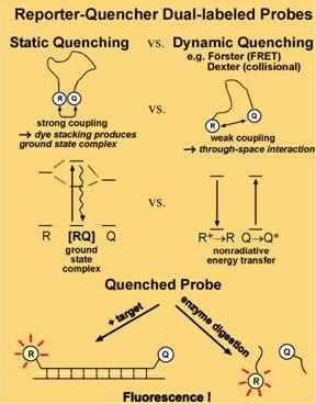
Comparison of static and dynamic quenching mechanisms
5.References
• J. Lakowicz, Principles of Fluorescence Spectroscopy, 2nd ed., Plenum, New York, 1999.
• M.K. Johansson, R.M. Cook, Chem. Eur. J. 2003, 9, 3466-3471.
• Long-Wavelength Rhodamines, Texas Red Dyes and QSY Quenchers.
.
Phycocyanin
Phycocyanin is a pigment from the light-harvesting phycobiliprotein family, along with allophycocyanin and phycoerythrin. It is an accessory pigment to chlorophyll. All phycobiliproteins are water soluble and therefore cannot exist within the membrane like carotenoids, but aggregate forming clusters that adhere to the membrane called phycobilisomes. Phycocyanin absorbs orange and red light, particularly near 620 nm (depending on which specific type it is), and emits fluorescence at about 650 nm (also depending on which type it is). Allophycocyanin absorbs and emits at longer wavelengths than Phycocyanin C or Phycocyanin R. Phycocyanins are found in Cyanobacteria (previously called blue-green algae). Phycobiliproteins have fluorescent properties that are used in immunoassay kits. Phycocyanin is from the Greek phyco meaning “algae” and cyanin is from the English word “cyan”, which is derived from the Greek “kyanos” and means blue-green.
Phycoerythrin
Phycoerythrin is a red protein from the light-harvesting phycobiliprotein family, present in cyanobacteria, red algae and cryptomonads.
Like all phycobiliproteins, phycoerythrin is composed of a protein part, organised in a hexameric structure of alpha and beta chains, covalently binding chromophores called phycobilins. In the phycoerythrin family, the phycobilins are: phycoerythrobilin, the typical phycoerythrin acceptor chromophore, and sometimes phycourobilin (marine organisms). Phycoerythrins are the phycobiliproteins which bind the highest number of phycobilins (up to six per alpha-beta subunit dimer).
Absorption peaks in the visible light spectrum are at 495 and 545/566 nm, depending on the chromophores bound and the considered organism. A strong emission peak exists at 575 ± 10 nm. (i.e., phycoerythrin absorbs slightly blue-green/yellowish light and emits slightly orange-yellow light.)
Phycoerythrin is an accessory pigment to the main chlorophyll pigments responsible for photosynthesis. The light energy is captured by phycoerythrin and is then passed on to the reaction centre chlorophyll pair, most of the time via the phycobiliproteins phycocyanin and allophycocyanin.
R-Phycoerythrin is useful in the laboratory as a fluorescence-based indicator for the presence of cyanobacteria and for labeling antibodies in a technique called immunofluorescence, among other applications. There are also other types of phycoerythrins, such as B-Phycoerythrin, which has slightly different spectral properties. B-Phycoerythrin absorbs strongly at about 545 nm (slightly yellowish green) and emits strongly at 572 nm (yellow) instead and could be better suited for some instruments. B-Phycoerythrin may also be less “sticky” than R-Phycoerythrin and contributes less to background signal due to non-specific binding in certain applications.
External links
